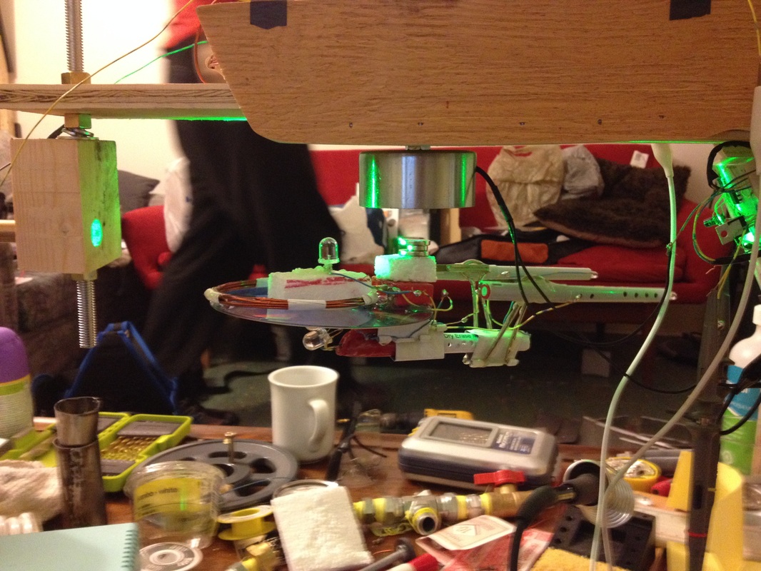
In the October of 2014 I built a levitation device based on the principle of electromagnetic suspension (as opposed to electrodynamic suspension) of a USS Enterprise suspended in air.
The main difference between EMS and EDS is that in EMS you have an electromagnet which attracts a ferromagnetic or magnetic object and the electromagnet is modulated via some sort of feedback to stabilize the position of the object being levitated. In EDS you apply a time varying magnetic field (by applying a time varying current in a coil), such that an induced eddy current in a nearby metallic but non-ferromagnetic object will cause it to be repelled much like a diamagnetic object. In essence, EMS pulls the object up against gravity and must rely on feedback for stabilization, and EDS repels the object up against gravity and thus has a self negative feedback. (Since a slight increase in separation will cause a decrease in the repulsion force, and gravity will bring it back down. Likewise a small decrease in separation increases the repulsion force and it returns to stable position).
However, the power consumption for an ordinary coil powered EDS system is far greater than EMS (Maglevs use both systems, the EDS Maglevs use neodymium magnets and/or superconducting coils to reduce power consumption).
For the sake of power consumption I decided to use EMS.
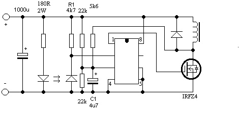
The circuit is actually designed by another guy online. I modified it heavily both in terms of electronics and optics. I used a laser diode and photodiode pair instead of IR LED and IR photodiode. The opamp is also upgraded (I used TL082 dual opamp). I also upgraded the main transistor with a logic level MOSFET so it can be fully driven with logic circuits.
Optics is only one of many methods to implement feedbacks in EMS. One can also use a Hall effect sensor, which has some advantages. See following circuit.
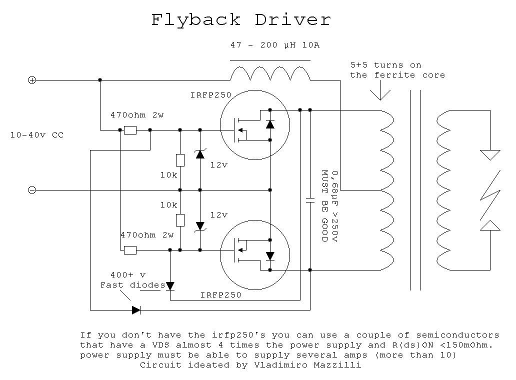
As for the wireless energy transfer part of the project, I used a zero-voltage-switching oscillator circuit popular in the HV community. I used a circuit similar to the one shown below.
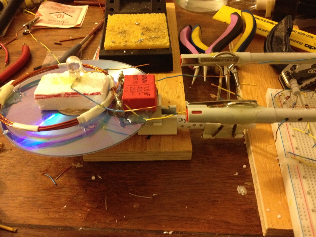
I used a pair of IRFP260N, 100 uH choke, and 12 VDC supply from computer PSU. The resonant coils are 3+3 turns primary coupled with 1 uF polypropylene (very important, because you don't want a RF lossy medium) capacitor, and 6 turn secondary with identical capacitor. The circuit can light up a 12W incandescent light bulb at about 10 cm, and light up a bunch of LEDs at up to 30 cm.
As a general rule, the maximum transfer distance is proportional to the coil diameters. My coils were roughly 15 cm in diameter. But of course, LEDs don't consume much power, so they can be lit up a bit further.
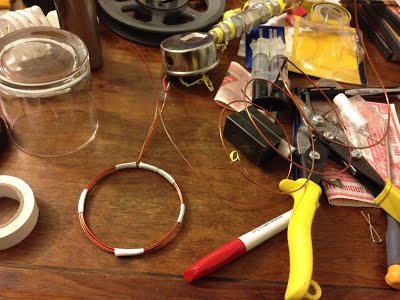
As for the physical layout of the ship, I built the resonant coil in the saucer section of the hull (noting the circular geometry of both), and the main LED arrays are tucked away into the two warp nacelles, with small holes drilled to simulate the effect of the warp engine (a blue glow) during operation. The most difficult part of this construction was the meticulous weaving of wires from the various parts of the ship and trying to reduce the visibility of these wires.
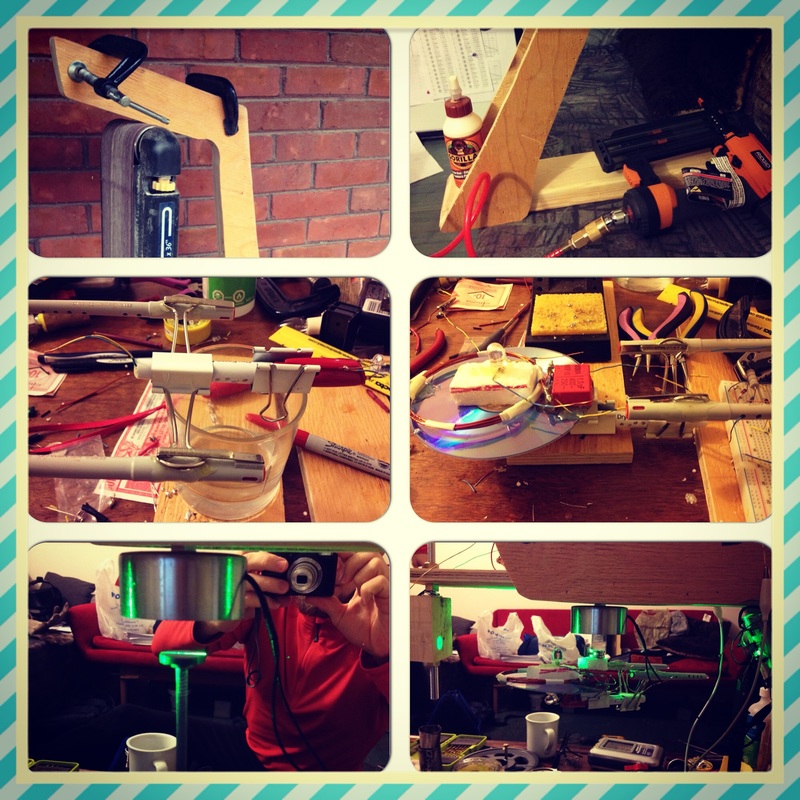
Here are some more pictures of the construction and testing of the levitating USS Enterprise.
